Flow
BNA Bypass Level Indicator
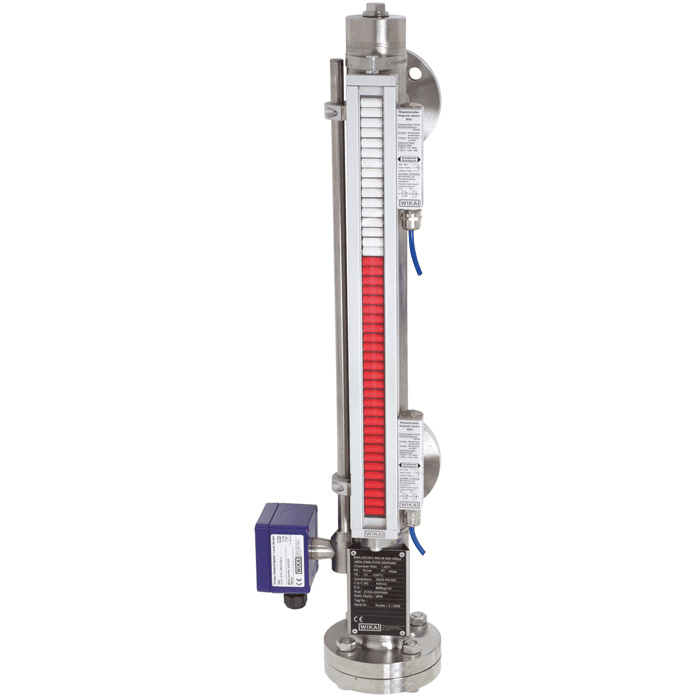
The bypass level indicator BNA consists of a bypass chamber, which, as a communicating tube, is connected laterally to a vessel via at least two process connections (flanged, threaded or welded). Through this type of arrangement, the level in the bypass chamber corresponds to the level in the vessel. The float with a built-in permanent…
| Max. pressure in bar | 40 |
|---|---|
| Medium temperature in °C | -196...+150 |
| Bypass chamber | Ø 42.2 x 2 mm |
The bypass level indicator BNA consists of a bypass chamber, which, as a communicating tube, is connected laterally to a vessel via at least two process connections (flanged, threaded or welded). Through this type of arrangement, the level in the bypass chamber corresponds to the level in the vessel. The float with a built-in permanent magnetic system, which is mounted within the bypass chamber, transmits the liquid level, contact-free, to the magnetic display mounted to the outside of the bypass chamber. In this are fitted, at 10 mm intervals, two-coloured plastic rollers or stainless steel flaps with bar magnets.
Through the magnetic field of the permanent magnetic system in the float, the display elements, through the wall of the bypass chamber, are turned through 180°. For an increasing level from white to red; for a falling level from red to white.
Thus the bypass level indicator clearly displays the level of a vessel without power supply.
| Datasheet WIKA bypass level indicator | DS_LM1001_GB_27552.pdf |
|---|
Request an offer
RECEIVE A QUOTE WITHIN 3 HOURS ON BUSINESS DAYS

Want more information?
Get in touch with edward our wika specialist

Edward van Doorn
Sales Director Europe

Product catalog
- Download our product catalog
- Download


