4 steps to: calibrate temperature measuring instruments
For this article we are going to assume that we are trying to calibrate a temperature measuring instrument with a stem portion, which is normally inserted into a pipe, a tank, or any other application where the insert reaches into the thing of which it is trying to measure the temperature. The measuring part of the instrument is always in the stem portion, so it is important that the calibration method heats up (or cools down) the stem portion in a reliable and stable way. This could be as simple as a cup of ice water, but in our specific industry the golden standard is either a dry block calibrator or a liquid bath calibrator.
As you would suspect, a liquid bath calibrator heats up a bath of liquid to a specific temperature and keeps it at that temperature. The calibrator has a very accurate temperature sensor and an indicator to show what the sensor indicates. Because the liquid bath may cause problems when the calibration has to be performed on the go, this type of calibrator is particularly useful when you have a stable working location. The liquid bath is also particularly useful for instruments with unusual shapes and dimensions, as these usually do not fit other into other calibrator designs.
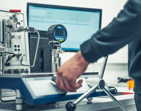
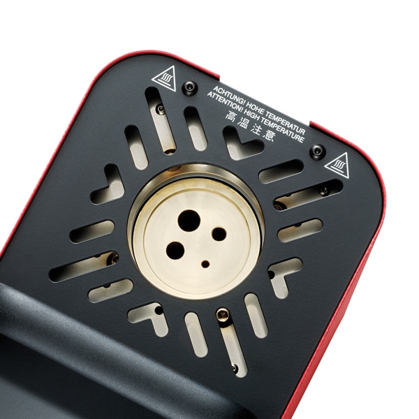
The dry block calibrator is very similar in design. The “dry block” is a metal hollow cylinder inside of the calibrator, where you can place the stem of the instrument into. The calibrator can be customized with different size inserts, to make sure that the stem of the instrument matches up with the inner diameter of the inside of the cylinder. This maximizes the heat transfer and the speed of the heat transfer. The image below shows the block with the different insert diameters, so called adapter sleeves.
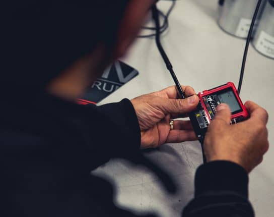
Okay, so let’s say we use a dry block calibrator by SIKA.
What are the steps to calibrate a resistance thermometer?
-
Check the instrument and the calibrator for flaws, cracks, dents or electrical issues.
Make sure they work! Be sure that no parts are damaged or compromised, as the calibration may be done at high temperatures. If the instrument or the calibrator is compromised in any way, this may cause dangerous situations. When something is faulty, send it for repair or replace it, DO NOT calibrate!
-
Make sure you have a clear plan for the calibration.
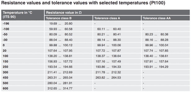
Temperature calibration is often done according to five points over the intended range of the instrument. In this case we will be using a resistance thermometer of accuracy Class B. Class B resistance thermometers (with a wire-wound sensor) are used for temperatures between -196 oC and +600 oC. So we know that we want to use five points in this range. But the dry block calibrator we are using can only simulate positive temperatures, so picking a negative temperature as one of the points is not a good idea. Let’s say we choose the five points as follows: 20 oC, 100 oC, 150 oC, 250 oC and 500 oC. We can take a look at the table (look at Class B) below to check the corresponding resistance values we can expect to see at those temperatures. When we raise the temperature and check what the resistance thermometer is outputting, these are the values we are going to be looking for. The output is in Ohm (Ω) They are 107.64-107.95 Ω, 138.20-138.81 Ω, 156.93-157.72 Ω, 193.54-194.66 Ω and 280.04-281.91 Ω. You can see clearly now how the range grows as the temperature increases.
-
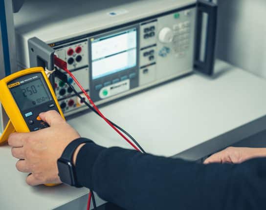
Check the five measuring points and write down what the resistance thermometer outputs.
We start with the first temperature point. Set the calibrator to the temperature you want manually or you can use one of the installed modes where it will do the temperatures automatically. We will do this calibration manually. The first setting is 20 oC. The calibrator will start to heat up. If the calibrator is a little older and you are trying to simulate very high temperatures, this may take a while! When the calibrator is up to the temperature we want it to be, we check that with the indicator of the calibrator. This should indicate exactly 20 oC, to the maximum amount of decimals it will be able to show. Then we check the output of the resistance thermometer and write down what we see. Then you compare this to the boundaries we set in step 2. Does the reading fall between the boundaries? Do this for all five measuring points and write down what the output is.
-
Take a look at the results! Is the instrument accurate?
Let’s say our results are what we see in the table below. In the first column we see what the (very accurate) calibrator indicates. The second column shows us what our instrument indicates in Ohm. Then the third column indicates the reading of the calibrator translated to Ohm and the fourth column shows how much the test instrument reading therefore deviates from the calibrator reading. The fifth column shows the allowed tolerance at each temperature point.
| Calibrator Reading (oC) | Test Instrument Reading (Ω) | Calibrator reading (Ω) | Deviation (Ω) | Tolerance (Ω) |
| 20.00 | 107.786 | 107.793 | -0.007 | ± 0.155 |
| 100.00 | 138.475 | 138.505 | -0.030 | ± 0.305 |
| 150.00 | 157.366 | 157.325 | +0.041 | ± 0.395 |
| 250.00 | 194.333 | 194.098 | +0.235 | ± 0.56 |
| 500.00 | 280.594 | 280.978 | -0.384 | ± 0.935 |
Clearly, the measurements are all well within the allowed tolerances. This means that the instrument is considered accurate according to its accuracy class. For this calculation we used the very useful calculator by FLUKE: PT100 Calculator | Fluke Calibration.
Related
More of the same